UID91900
НюНы44
ҪрЗ®143015
Ҫ»ТЧіПРЕ¶И0
ЦчМв34
МыЧУ1703
ЧўІбКұјд2004-10-9
QQ ЧоәуөЗВј2024-6-9
ёЯј¶»бФұ

Ҫ»ТЧіПРЕ¶И0
ЧўІбКұјд2004-10-9
|
ФӯМыУЙ killkill УЪ 2007-4-28 20:26 ·ўұн
ДъІ»»бЦ»»бёшБҙҪУ°ЙЈ¬ЗлЛөЈ¬ОТПҙ¶ъ№§МэЎЈ
әГЈ¬ОТЧӘМщ№эАҙ
Let's take the case of two digital signals, A and B, that toggle between a low and a high state. These are shown at the top of fig.6. If these signals are high-pass filtered (as they would be by an isolation transformer), they appear as the waveforms in the center of fig.6. If these signals are also low-pass filtered (as they would be by a digital interface), the waveform assumes the shape at the bottom of fig.6. Note that, at the third transition (marked "3T"), the bandpass filtering causes the edges to have a slope at the zero crossing transition. This slope, combined with the voltage difference, causes a time difference between the zero crossing points of signals A and B. A low-pass filter at 8MHz and a high-pass filter at 50kHz produces a time difference between A and B of 1106ps (1.106ns). By contrast, the low-pass filter alone would produce a timing difference of 2.7ps. 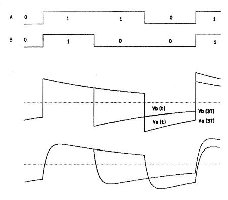 Fig.6 Two perfect digital data signals, A & B (top); waveforms of A & B after passing through typical high-pass filter (middle); waveforms of A & B after passing through typical low-pass and high-pass filter combination (bottom). While these values apply to a particular segment of the digital interface signal and do not represent the jitter itself, they clearly show the considerable damage caused by a high-pass filter in the data transmission path. Moreover, while increasing the low-pass filter cutoff frequency to 20MHz brings the timing difference caused by the low-pass filter alone to infinitesimal amounts, it only reduces the timing difference caused by the filter combination to 442ps. Clearly, a wide-bandwidth interface is essential for low-jitter transmission of digital audio. Fig.6 Two perfect digital data signals, A & B (top); waveforms of A & B after passing through typical high-pass filter (middle); waveforms of A & B after passing through typical low-pass and high-pass filter combination (bottom). While these values apply to a particular segment of the digital interface signal and do not represent the jitter itself, they clearly show the considerable damage caused by a high-pass filter in the data transmission path. Moreover, while increasing the low-pass filter cutoff frequency to 20MHz brings the timing difference caused by the low-pass filter alone to infinitesimal amounts, it only reduces the timing difference caused by the filter combination to 442ps. Clearly, a wide-bandwidth interface is essential for low-jitter transmission of digital audio. |
|

 ҫ©№«Нш°Іұё 11010602010207әЕ
( ҫ©ICPЦӨ041102әЕЈ¬ҫ©ICPұё09075138әЕ-9 )
ҫ©№«Нш°Іұё 11010602010207әЕ
( ҫ©ICPЦӨ041102әЕЈ¬ҫ©ICPұё09075138әЕ-9 )


 №·ЧРҝЁ


 ·ўұнУЪ 2007-4-28 11:12


