UID405168
НюНы246
ҪрЗ®1227124
Ҫ»ТЧіПРЕ¶И0
ЦчМв974
МыЧУ17961
ЧўІбКұјд2007-4-9
ЧоәуөЗВј2025-2-19
әЛРД»бФұ

Ҫ»ТЧіПРЕ¶И0
ЧўІбКұјд2007-4-9
|
[s:97] [s:97]
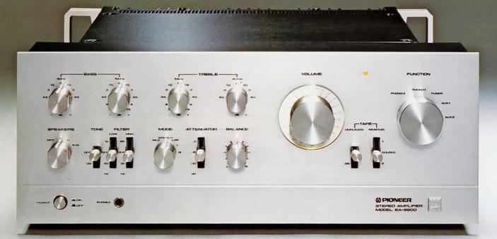
| [size=+3]Pioneer SA-9900 | | | 185,000yen(around the 1975 time) |
[size=-1]ЎЎ
The Integrated Amplifier which investigated the Oide power and a Low-noise-izing and adopted the still more unique sub- termination scheme.
The sub- termination scheme was adopted, input terminals were united with the equalizer substrate, and the shielding wire which ties a phone termination and an equalizer termination is eliminated. This has prevented the failure of the high region property under the influence of the stray capacity of shielding wire.
The power amplifier part has adopted the whole page hardwired-connection pure complimentary OCL circuitry by a three-step Darlington connection, and the output stage is taken as the parallel push pull scheme.
Moreover, stability sufficient by controlling the direct current component to a speaker termination by two steps of differential amplifier and a bias compensation circuit, even if there is a transition of an exterior temperature etc. has been acquired.
The improvement in a nakedness property is aimed at by extending the operating range of a transistor by two constant current circuits, and taking the large nakedness property of a circuitry, and also applying NFB not only with NFB from an output stage but differential moderate circles.
Moreover, by applying NFB from an output stage, a failure and instability of a transient are canceled and the phase shift in super-low-pass one is lost by giving a big time constant further to this circuitry.
While a transition of the idle current by variation of supply voltage is suppressed by the constant current circuit,Adoption of the newly developed bias supplying system could perform the fixed build-out also to the difference of temperature between each transistor produced in a self-over-temp of a transistor, and a transitional crossover distortion is eliminated by the idle current stabilized from the high power time till the minute output.
Furthermore, the crossover distortion by this stage is canceled by floating from the middle point and carrying out the Class-A operation of the emitter resistor of the driver stage till a remarkable large swing.
While the property selected carefully and used for the power transistor the good thing which has a strong set destructive intensity, it took all possible measures by adoption of the large-sized radiator etc., and also the trouble is also coped with in an electronic formula protection network, a current-limiting circuitry, etc. by relay.
Furthermore, whenever it has adopted the newly developed temperature detector and the temperature of a radiator turns into 85 degrees or more, output-stage supply voltage is controlled and the temperature of the radiator is suppressed within fixed.
It serves as a design which reduces the noise level on Hearing impression while the first rank uses an equalizer circuitry as the differential amplifier by low-noise FET and it attains a stabilization of the output middle point. The 2nd step of voltage amplification stage obtained the good high amplification degree of the linearity using the constant current load intensity, and has improved the distorted property. Moreover, the modification of the SN ratio is aimed at because the transistor by which noise sorting was carried out uses.
The high voltage of ЎА48V is supplied to the circuitry, and sufficient dynamic margin is secured. Moreover, very little nichrome metal film resistor with error and styrene capacitor were used for the NFB element for a RIAA curve, and the outstanding property has been acquired.
The level adjustment up to -12dB is possible for the input of Phono2. 6dB is performed in a NFB circuitry and -12dB is performed in sy copy power volume from -6dB. When it extracts to 6dB or more, a maximum permissible input becomes large with about double 1V.
Moreover, the impedance switching of a four-point change is also carried.
A control circuit also places the differential-amplification part of FET by which the direct current NFB is applied to the first rank 100%, and the power source also supplies ЎА48V for it by 2 power-source schemes. The SN ratio was pulled up by adoption of FET, and also the it1 noise at the time of a switchpoint switching is prevented with 2 power-source schemes.
Since a voltage amplification part also raises the nakedness property of a circuitry as a constant current load intensity like an equalizer circuitry and a bootstrap circuit is not used, a low-pass phase response and transient are raised.
The twin tone control scheme is adopted as a tone circuitry. If it is an operation of only a main and is an operation of only a factice as a general tone control, a super-high region and super-low-pass control is possible. Furthermore, a broad control is possible by combining a main and a factice.
In these two controls, the main serves as a NFB type, and the factice has become CR type. Moreover, the tone control ON/OFF switchpoint is carried.
The full-scale attenuator type volume by the high precision printed resistance of 22 contacts which gave the decibel window of a 2dB step is adopted as a volume so that the Direct reading of the attenuation can be carried out. This decibel window fraction is illuminated in the edge light.
Moreover, the lever type attenuator whose change is possible is also carried in three steps.
Two 22,000-micro F mass electrolytic capacitors are carried in the power-source part.
The low cut / high cut-off filter of a two-step switching type are carried.
The duplicate switchpoint is carried and tapes dubbing can be performed from 2 to 1 to tapeses 1-2 by turning ON a switchpoint.
The data which surveyed the product for every one product is attached.
|
.JPG) | | | .JPG) |
| [size=-1]Rating of a mode[size=-1] |
| [size=-1]Form | [size=-1]Stereo Integrated Amplifier | | [size=-1]<Power amplifier part> | | [size=-1]Circuit system | [size=-1]Differential three-2 steps of step Darlington ҘСҘйҘмҘлҘЧ push pull pure complimentary OCL | [size=-1]Effective output
(Both channel drive, 20Hz - 20kHz) | [size=-1]110W+110W (4ohm)
110W+110W (8ohm) | | [size=-1]THD (20Hz - 20kHz) | [size=-1]0.1% or less (at the time of an effective output)
0.04% or less (at the time of 55W output 8ohm)
0.04% or less (at the time of 1W output 8ohm) | | [size=-1]Cross modulation distortion | [size=-1]0.1% or less (at the time of an effective output)
0.04% or less (at the time of 55W output 8ohm)
0.04% or less (at the time of 1W output 8ohm) | | [size=-1]Output bandwidth (IHF, both channel drive) | [size=-1]5Hz - 40kHz (0.1% of distortion) | | [size=-1]Frequency characteristic | [size=-1]10Hz-80kHz+0 -1 dB | | [size=-1]Input sensitivity/impedance | [size=-1]Power amp in: 1V/50kohm | | [size=-1]Output-terminal | [size=-1]Speaker A-B: 4ohm-16ohm
Speaker A+B: 8ohm-16ohm
Headphone: 4ohm - 16ohm | | [size=-1]Dumping factor | [size=-1]30 (20Hz - 20kHz) or more | | [size=-1]S/N | [size=-1]110dB or more (IHF, A network, a short circuit) | | [size=-1]<Preamplifier part> | | [size=-1]Circuit system | [size=-1]Equalizer amplifier: Positive/negative 2 power source,
FET differential three-step hardwired-connection Class-A SEPP per step
Control amplifier: Positive/negative 2 power source,
the FET differential three-step hardwired connection per step | | [size=-1]Input sensitivity/impedance | [size=-1]Phono1:2.5mV/50kohm
2:2.5-10mV of Phono / 35kohm, 50kohm, 70kohm, 100kohm
Tuner, Aux1, 2, Tape PB1, 2:150mV / 50kohm | [size=-1]Phono maximum permissible input
(0.1% of a THD, 1kHz) | [size=-1]Phono1:500mV
Phono2:500mV-1.0V | | [size=-1]An Output voltage/impedance | [size=-1]Tape Rec1, 2:150mV
Pre out: 2V/1kohm | | [size=-1]THD (20Hz - 20kHz) | [size=-1]0.05% or less | | [size=-1]Frequency characteristic | [size=-1]Phono(RIAA deflection): 30Hz-15kHzЎА0.2dB
Tuner, Aux, and Tape PB:7Hz-40kHz+0 -1 dB | | [size=-1]Tone control | [size=-1]1.5dB step | [size=-1]Bass | [size=-1]sub: ЎА4.5dB (50Hz)
main: ЎА7.5dB (100Hz) |
| [size=-1]Treble | [size=-1]sub: ЎА4.5dB (20kHz)
main: ЎА7.5dB (10kHz) |
| | [size=-1]Filter | [size=-1]Low: 15Hz, 30Hz, 12dB / oct
High: 8kHz, 12kHz, 12dB / oct | | [size=-1]Muting | [size=-1]0 -15dB-30dB | [size=-1]S/N (IHF, A network)
Short circuit | [size=-1]Phono: 70dB or more
Tuner, Aux, Tape PB: 95dB or more | | [size=-1]<Synthesis> | | [size=-1]The semiconductor used | [size=-1]Transistor: 74 pieces
FET: Ten pieces
Diode,others: 33 pieces | | [size=-1]AC outlet | [size=-1]Power-switch interlock: Two lines
Power-switch un-interlocking.: One line | | [size=-1]Supply voltage | [size=-1]AC100V, 50Hz/60Hz | | [size=-1]Power consumption | [size=-1]270W (rate)
730W (maxima) | | [size=-1]Dimensions | [size=-1]Width 420x height 165x depth of 403mm | | [size=-1]Weight | [size=-1]20.0kg |
|
|
|


 ҫ©№«Нш°Іұё 11010602010207әЕ
( ҫ©ICPЦӨ041102әЕЈ¬ҫ©ICPұё09075138әЕ-9 )
ҫ©№«Нш°Іұё 11010602010207әЕ
( ҫ©ICPЦӨ041102әЕЈ¬ҫ©ICPұё09075138әЕ-9 )


 №·ЧРҝЁ
 ·ўұнУЪ 2011-6-21 21:54


 ұдЙ«ҝЁ
 ВҘЦч
ВҘЦч

.JPG)
.JPG)
.JPG)
.JPG)
.JPG)


