家电论坛

京东旗舰店
 注册  找回密码

QQ登录

只需一步,快速开始

手机号码,快捷登录

查看: 6298|回复: 19

BASF公司技术公告#4 EQ技术发明笔记 中文翻译全文 BASF说了,120uS铬带不是二类带基

[复制链接]

213

主题

3481

帖子

101

威望

超级会员

Rank: 6Rank: 6Rank: 6Rank: 6Rank: 6Rank: 6

交易诚信度
0
注册时间
2011-12-4
发表于 2015-11-23 16:00 | 显示全部楼层 |阅读模式

马上注册 家电论坛,众多有奖活动等你来参与!

您需要 登录 才可以下载或查看,没有账号?注册

x
本帖最后由 全中文说明书 于 2015-11-24 09:14 编辑

译者注:本文为德国BASF公司官方发布的公告文献PDF文件的翻译,其中详细描述了盒式磁带,开盘机磁带因为微分效应和高频损耗相互作用产生的天然物理特性和相对应EQ均衡播放原理的形成,以及几种材料磁带的先后发明过程,文章最末尾介绍了chromium dioxide120磁带的由来和技术成因。本文第二楼是英文全文。

BASF公司的这篇文档详细披露了在盒式磁带中,历史上铬磁带发展的三个阶段,三种铬带的研制过程及性能。也可从中看出第一种和第三种铬带使用120uS,而第二种铬带使用70uS均衡的具体原因。由此可以排除流行于市面的商业预录磁带中标识有chromium dioxide120,CrO2 120之类似标识的磁带,是直接采用70uS的“二类带基”的可能性。

BA.JPG

技术公告4
1.JPG
1819年一次演讲中,汉斯·克里斯蒂安·奥斯特公布了他出乎意料的发现,在导体内通过电流,会在导线周围产生磁铁般作用。在183110月,法拉第发现相反的效果:在导线组成的线圈旁边移动磁体会在线圈中产生电流;更快地移动磁铁,就会产生更大的电流。这两项发现导致了电力的发展作为能量的介质。今天,我们通过水或者蒸气的压力带动连接着巨大的磁铁的转动轴发电。轴和磁铁被导线制成的线圈包围。如果电机被输入电流,电流进入电机的线圈,通过轴上的磁铁作用,可以带动钻头,转动转盘。

法拉第也发现了应用磁带来录制和播放,磁头实际上是内部缠绕铁丝的电磁铁。当音乐被转换成电流,电流被发送到磁头,去产生磁铁的磁性印刷图案一样弄到磁带上。

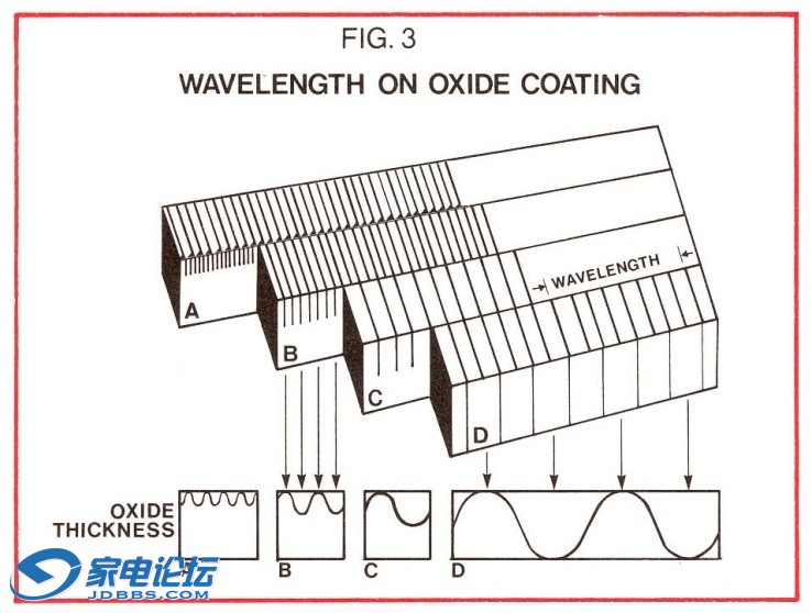
当录音磁带在磁头上经过,磁带上的磁性印记在磁头产生一个电流经过放大器放大后馈送给扬声器。磁头感应出的电流(它的输出),并不是依据在磁带上的磁信号的强度,电流强度取决于在磁通水平的变化率,或者,换言之,就象快速地将磁性印记移动通过磁头,就如同在法拉第线圈一样。录制好的磁带不移动经过磁头,磁头是没有感应信号的。因为高频率具备比低频率更强的印记(参照图3)它们具备有更大的变化速率(它们看起来可以等同“移动更快”)因此,它们具有更大的输出幅度。在电压方面,输出量的增加是以每倍频程6分贝----也就相当于每次频率增加两倍输出幅度也增加两倍。为了补偿这个增大的输出量,(1A)一个磁带录音机的重放部分具有内置的斜率衰减电路(1B),使得增加的和衰减的部分抵消“均衡”成为一个平坦的频率响应(1C)。这样,均衡祢补了输出的差异而使它们各频段相等。然而,随着频率的增加,并且磁印记(波长)之间的距离变短,高频损耗等因素,再加上磁带速度过慢,过宽的播放磁头缝隙,这些磁带上的限制导致6分贝/倍频输出的增加量停止下来,并且开始下降。为了解决这个问题,在衰减的斜率(B)下陷特定的频率点,使得高频自然输出升高祢补了高频的损失。

BASF EQ 图1.jpg

这第一种氧化铁磁带上造成的每倍频6分贝的增加量的消失位置,位于一个相对低的频率,是因为盒式磁带的磁带移动速度远远低于开盘式录音机。输出增量曲线开始转向下降到3分贝的位置就是1326.3HZ的位置,因此,“均衡”衰减(B)下陷点在这个频率。在电子工程方面,这个转折点是用“120微秒时间常数”(uS微秒,百万分之一秒)来表示。
造成输出衰减的主要原因见图,1A是间隙损耗,这是由于表面凹凸损耗和磁性涂层的厚度共同原因,虽然短的波长产生的频率越来越高,因此,产生了更大的电流在播放磁头,当磁头开始很难读取它们的时候,短波长信号输出就开始衰落,因为磁带的粗糙度也因为它们持有的磁性能量的额度不足以能够到达磁头工作缝隙,因为与磁场距离的增加导致磁强度按指数滑落,因此由于表面粗糙造成的即便是轻微的磁带离开磁头的运动将会导致输出的损耗,而这些损耗在短波长中最明显。改进效果是最显著的,就是磁带制造商已经能够通过在生产过程中硬性碾压和抛光来增加一些磁带的制剂材料的高频特性,而不必诉诸去改变氧化物的矫顽力。
BASF EQ 图3.jpg

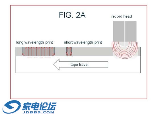
输出的损耗是由于磁带的厚度这种其它形式的间隙损耗存在,短波的磁场输出更加靠近磁带的表面,因为短波的磁性图案印记要录到涂层更深处,就犹如录音磁头离开录音区域去改变磁性图案印记的方向一样困难。虽然这也适用与长波长,有一个“正确排列”非常大的区域的磁通,长波长相比短波长,可以产生更大的磁性图案印记。(2A)。在涂层深处改变磁印记图案容易造成相互抵消,直到他们更接近于表面。(录音过程中减小偏磁使得更多短波能量接近表面并且减小短波长由于自我擦除造成的损耗。但是偏磁的减小也降低了磁化渗透入涂层导致了长波的低输出/高失真,因为被适当磁化的涂料更少了,增加偏磁能磁化更多的涂料,到了一定程度,但是也能驱使短波长打印到更深的涂层并且也增加了自擦除,降低了高频输出。)更薄的涂层提高了高频输出,但是低频输出会损失。典型盒式磁带的标准厚度的涂层也意味着播放磁头失去解决短波由于损耗点开始3分贝之后在1326.3HZ位置间隙损耗的能力,这就是为什么下降均衡在图1B是陷波在这个位置的原因。

BASF EQ 图2A.jpg

二氧化铬磁带的发明显著改进盒式磁带的高频响应,是一个全新的氧化物磁带,高频效能相比铁氧化物材料更高超。氧化物的粒子均匀特性允许磁带的表面更加平滑,并且它更高的矫顽力允许它承受更高电平的高频能量。在其推出的同时,然而,这磁带作为一种音乐介质得到最大的抱怨就是它的磁带嘶嘶声。
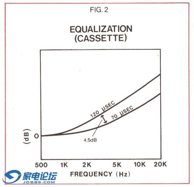
磁带工程师决定牺牲较高的输出或者说是铬材料的“SOL(饱和输出电平)以便减少磁带的嘶嘶声。他们决定移动CrO2材料过渡点到一个更高的频率2.273.6HZ,或者也可称为70-uS EQ70-uS的时间常数是有利的,因为它允许6分贝/倍频程的斜率(B)的继续增长,并且对于影响来说,“补偿”较少的高频(2);并且较少的高频补偿意味着更少的磁带嘶嘶声被被同时提升。在盒式磁带主要听觉差别不在于高偏磁或者普通偏磁,而是在于70120微秒均衡的改变:70-uS EQ将始终发生4.5分贝以下的磁带嘶嘶声。二氧化铬,和二氧化铬相当的,铁铬双层,和金属颗粒磁带都是使用70-uS播放EQ


BASF EQ 图2.jpg


还有一个盒式磁带播放的时间常数是除了120uS70uS之外未被广为人知:3180uS(50HZ过渡点)。提高最低的低频频率,以至可能出现嗡嗡声或者低频噪音这样的问题,低于50赫兹的频率在播放的时候略微下滑。为了祢补这方面的滑落,在录音过程中录音EQ电路给这些频率以录音补偿使之在播放的时候均衡。但是一些制造商放弃3180-uS时间常数标准,因为他们感觉为了更好的低频响应设计的新型磁头是会受到这个时间常数的限制的。一台有3180-uS EQ的卡座录制的磁带在没有这个EQ的卡座上播放会产生太多的低音,除非音调控制可以把它降低到一定的程度。

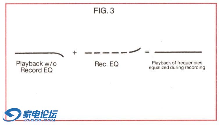
播放均衡是制订了标准化的,所以在任何一台机器上录制的磁带将会在所有的机器上播放出相同的声音,因为所有的机器拥有相同的精确的播放EQ电路。由于磁头的种类,电路,和磁带制剂材料不同,任何方面的调整是用来形成录音中的均衡,或者使用特定的磁带在特定的录音机中进行“预加重”的。这些调整是为了形成录音EQ,这样,所有的卡座依据标准的播放EQ电路,在播放中的频率响应就是平坦的了。(3)。在录音前,所有的卡座使用录音EQ的一些定量给高频以提升,因为高频的损耗不能简单通过使用播放EQ电路来降低斜率的方法来足够补偿。在录音之前提升高频信号再搭配上播放EQ也防止了增加磁带的嘶嘶声,但是录音EQ一定不能这么大幅度,因为提升过高会导致由于磁带的超载造成的明显失真或者饱和。这样,尽管播放EQ电路是所有机器上的标准,每个机器有个可调节的录音EQ用来保证在标准的播放均衡器中频率响应的平坦。

BASF EQ 图3A.jpg

开盘磁带机也使用均衡,并且更快的磁带速度意味着更少的频率急剧变化。然而,同时出现的情况是,因为磁带速度的各种品种,因为不同的标准存在----NAB,DIN,IEC,CCIR。大多数美国和日本的开盘卡座符合NAB标准,有些类似与那些盒式磁带卡座。NAB和其它的标准,欧洲的标准主要的区别在于NAB允许播放中的6分贝/每倍频斜率继续到更高的过渡频率,以降低更多的磁带嘶嘶声,并且为了防止嗡嗡声问题和低频噪音,播放中不提升那么多低音量。NAB标准要求3¾,7½,每秒15英寸速度(ips)的磁带在3180-uS EQ的低频响应滑落;高频时间常数3¾磁带是90uS(1.768HZ) 15 IPS磁带是50uS(3.183Hz)At 30 IPS没有低频衰减,17.5uS(9.095Hz)是其高频EQ


欧洲标准,DIN(德国)IEC(国际),或者是COIA(法国)使用不同的时间常数(4). 3 ¾ IPS磁带采用了NAB相同的速度。但是其它所有带速的磁带是没有低音滚降的。磁带的高频时间常数是70uS(2274Hz)15iPS磁带是35uS(4574Hz)     

一些专业机的设计使得NAB或者IEC的播放EQ其中一个选择是可采用的。一个开盘录音机上NAB EQ的运用是在录音均衡上使用一个低音补偿提升播放中的3180uS的滚降损失部分。NAB时间常数也比IEC时间常数要求更多的高频录音预加重,因为高频的翻转点或者说是过渡点发生在更高的频率可以避免更多的嘶嘶声(70uS的时间常数盒带相比120uS的来说有小了4.5分贝的低噪音)

缺陷就是额外的预加重补偿促使高频接近失真或者饱和点,在7 ½ips磁带中,相比333HZ音调电平,14000Hz音调将会提升大约68分贝那么高幅度。3 ¾ ips磁带是10-12分贝;并且同样在盒带速度下相当于16-20分贝提升量。通常音乐中包含大约相比中频小40分贝的这么高频率,但是现场音乐和高质量的光盘可以包含更大的高频能量,当这个更大的高频能量得到一个额外的16-20分贝的补偿,它就有可能让磁带饱和。

6分贝/倍频的斜率转换到不太陡峭的曲线变化,是通过磁带卡座内置的电子阻容网络决定的,转折频率有以下公式决定。

其中T是时间常数,以微秒表示,并且时间常数值是一个整数比如70或者120。时间常数自己取决于RC网络中的电阻乘以电容的数值。比如,10000欧电阻乘以一个0.007微法电容将要得到一个时间常数:
10,000 ohms x (7 x10 farads) = 70 x 106 seconds = 70 μs

其次微秒所指的时间,是当所有其它数值相互抵消的时候,电阻乘以电容的时间单位。


1970年初期杜比B降噪很明显将变成高保真盒式录音机的标准的时候,BASF公司的工程师非常后悔移动到70-uS均衡,因为杜比NR降噪可以降低磁带噪音10分贝。如果二氧化铬磁带有保留在120-uS均衡,并且让杜比NR解决嘶嘶声的话,二氧化铬磁带将拿回为了降低嘶嘶声而牺牲掉的4.5分贝的SOL电平。

当二氧化铬磁带应用在高速磁带复制机上的时候给了自身一个机会,BASF公司确信A&M唱片公司发行警察乐队的“Synchronicity”专辑在播放均衡在120uS EQ的盒式磁带上,BASF铬带的无与伦比的低噪音通过附加杜比B降噪和增加了SOL电平给予磁带的大动态范围使它非常接近TYPE IV金属磁带使用杜比NR时候的效果。


翻些DAT机MD机中文说明书,DAT磁带代录,调音等,3D打印仓盖,旋钮,见fzmcu.taobao.com
回复

使用道具 举报

213

主题

3481

帖子

101

威望

超级会员

Rank: 6Rank: 6Rank: 6Rank: 6Rank: 6Rank: 6

交易诚信度
0
注册时间
2011-12-4
 楼主| 发表于 2015-11-23 16:00 | 显示全部楼层

During a lecture in 1819, Hans Christian Oersted discovered to his surprise that electrical current running through a wire made the wire act like a magnet. In October, 1831, Michael Faraday discovered the reverse effect: that moving a magnet in and out of a coil of wire produced electric current in the coil; and the faster the magnet moved, the more current was produced. These two discoveries led to the development of electricity as a medium of energy. Today we generate electricity by using water or steam pressure to turn shafts with huge magnets attached to them. The shafts and magnets are surrounded by coils of wire so that, as the shaft turns, the moving magnets produce electric current in the coils. If an electric motor is plugged into the current, the electricity flows into the motor’s coils and turns the magnets on the motor’s shaft: the drill drills, the turntable turns.


Faraday’s discovery also applies to tape recording and playback. A tape head is actually an electromagnet with coils of wire inside. When music is translated into electrical current, the current is sent to the head to act as a magnet putting magnetic print patterns on the tape.

When recorded tape runs past the playback head, the magnetic prints on the tape create a current in the head that is amplified in the chain of audio components and is finally fed to the speakers. The current induced in the head (its output), however, does not depend directly on the magnetic signal on the tape; the current depends on the rate of change in the flux level, or, in other words, on how fast the magnetic prints move past the head, just as in Faraday’s coil. Recorded tape not moving past the head generates no signal in the head at all. Since high frequencies have more prints than low frequencies (cf. FIG. 3, “Inventor’s Notebook” #3), they have a greater rate of change (they seem to be “moving faster”) and, consequently, they have more output. In terms of voltage, the output increases at a rate of 6dB per octave—twice as much output every time the frequency is doubled. To compensate for this increasing output (FIG. 1A), the playback section of a tape recorder has a decreasing slope built into its circuitry (FIG. 1B) so that the increase plus the decrease is “equalized” for a flat response (FIG. 1C). Equalization makes up for the differences in output by making them equal. However, as frequencies increase and the distances between prints (wavelengths) grow shorter, high frequency losses due to such factors as spacing losses in addition to slow tape speed, wide playback gaps, and limitations in the tape cause the 6dB/octave output increase to level off and begin to drop. To solve this problem, the effect of the decreasing slope (B) is removed at a particular frequency point so that the natural high frequency output increase makes up for the treble losses.

The first ferric oxide tapes made for cassette recorders began to lose their 6dB/octave increase at a relatively low frequency because the cassette tape moved much more slowly than open-reel recorders. The output increase dropped 3 dB at a transition point of 1,326.3 Hz, so the “equalization” decrease (B) was removed at this frequency. In electronic engineering terms, this transition point was achieved with “a time constant of 120 microseconds” (μs, one millionth of a second).

The chief reason for the decrease in output seen in FIG. 1A is spacing loss, which is a combination of losses due to surface irregularities and to the thickness of the magnetic coating. Although short wavelengths occur with increasing frequency and, therefore, produce more current in the playback head, short wavelengths begin to lose that output when the head begins to have difficulty reading them because the roughness of the tape and because the amount of magnetic energy they hold can no longer reach the head gap. Magnetic strength falls off exponentially as distance from the magnetic field increases, so even slight movements of the tape away from the head due to surface roughness will cause losses in output, and these losses are most apparent at short wavelengths. This effect is significant enough that tape manufacturers have been able to increase high frequency output of some tape formulations by polishing the tapes through hard calendering during the production process without having to resort to changes in the coercivity of the oxide.

Loss in output due to the thickness of the tape is the other form of spacing loss. Magnetic output from short wavelengths is more effective closer to the surface of the tape because the short wavelength patterns deeper in the coating changed the direction of their magnetic patterns as they left the recording area of the record head. Although this is also true for long wavelengths, there is a much greater area of “correctly aligned” flux with the bigger magnetic patterns that long wavelengths produce than short wavelengths can produce (FIG 2A). The changed flux patterns deep in the coating tend to cancel each other out until they get closer to the surface. (Decreasing the bias during recording brings more short wavelength magnetic energy closer to the surface and reduces short wavelength loss due to self-erasure, but the bias reduction also reduces the penetration into the coating and results in lower output/higher distortion from the long wavelengths because less pigment is properly magnetized. Increasing bias magnetizes more pigment, up to a point, but also drives the short wavelength prints deeper into the coating and increases self-erasure with a reduction in high frequency output). Thinner coatings improve high frequency output, but at the loss of low frequency output. The standard coating thickness typical of cassette tape means that the playback head loses its ability to resolve short wavelengths due to spacing losses by 3 dB at 1,326.3 Hz, and that is why the downward equalization in FIG. 1B is removed at that point.

The invention of chromium dioxide tapes significantly improved cassette high frequency response with a totally new kind of tape oxide that was more efficient at short wavelengths than ferric oxide formulas. The uniformity of the oxide particles allowed smoother tape surfaces, and its higher coercivity allowed it to accept higher levels of high frequency energy. At the time of its introduction, however, the biggest complaint of the cassette as a music medium was its tape hiss.
Tape engineers decided to sacrifice the higher output or “SOL” (saturated output level) of chrome in order to reduce tape hiss. They decided to move the transition point of CrO2 to a higher frequency of 2,273.6 Hz, or 70-μs EQ*. The time constant of 70-μs is advantageous because it allows the 6dB/octave slope (B) to continue longer and, in effect, “boosts” fewer high frequencies (FIG. 2); and less high frequency boost means less tape hiss gets boosted at the same time. The major audible difference between cassette tapes is not in high or normal bias, but in 70- or 120-μs equalization: the 70-μs EQ will always provide about 4.5 dB less tape hiss. Chromium dioxide, chrome-equivalent, ferrochrome, and metal particle tapes all use 70-μs playback EQ.


There is another cassette playback time constant in addition to 120 μs and 70 μs that is not as widely known: 3,180 μs (50-Hz transition point). Instead of boosting the lowest bass frequencies so much that there may be problems with hum or low frequency noise, those frequencies below 50 Hz are rolled off slightly on playback. To make up for this roll-off, the record EQ gives those frequencies a boost during recording equal to the playback roll-off. Some manufacturers, however, are abandoning the 3,180-μs time constant standard because they feel that new head designs for better low frequency response are restricted by this time constant. A tape recorded on a machine with the 3,180-μs EQ and played back on a deck without it will have too much bass unless a tone control can reduce it to a degree.

Playback equalization is standardized so that any tape recorded on any one machine will sound the same on all machines when it is played back because all machines should have exactly the same playback EQ. Since the types of heads, circuitry, and tape formulations do differ, any adjustments are made to recording equalization or ‘pre-emphasis” in particular recorder using a particular tape. The adjustments are made to record EQ so that the frequency response on playback is flat according to the standard playback EQ that all decks follow (FIG. 3). All decks use some amount of record EQ to give the high frequencies a boost before recording because the high frequency losses cannot be compensated enough simply by removing the decreasing slope with playback EQ. Boosting the high frequencies before recording also avoids increasing the tape hiss that accompanies playback EQ, but the record EQ must not be so great that it boosts the highs to noticeable distortion or saturation caused by overloading the tape. So, while playback EQ is standard on all machines, each machine has an adjustable record EQ that is used to insure flat frequency response at the standard playback equalizations.


Open reel tapes also use equalization, and the faster speeds available mean less drastic frequency alteration. Complications arise, however, because of a variety of speeds and because of different standards—NAB, DIN, IEC, and CCIR. Most American and Japanese open-reel decks conform to NAB standards somewhat similar to those used in cassette decks. The chief difference between the NAB and the other, European, standards is that the NAB allows the 6dB/octave slope in playback to continue to a higher transition frequency to reduce more tape hiss, and the bass does not receive as much playback boost in order to avoid hum problems and low frequency noise. NAB standards call for a 3,180-μs EQ roll-off for the bass for 3? , 7 ? , and 15 inches per second (ips); the high frequency time constant is 90 μs (1,768 Hz) for 3? and 50 μs (3,183 Hz) for both 7? and l5 ips. At 30 ips there is no bass attenuation; 17.5 μs (9,095 Hz) is the high frequency EQ.


European standards, known as DIN (German), IEC (international), or COlA (French) use different time constants (FIG. 4). The 3 ? ips speed uses the same as those of the NAB, but other speeds have no bass roll-off at all. High frequency time constants are 70 μs (2,274 Hz) for 7? ips and 35 μs (4,547 Hz) for 15 ips.

Some professional machines are designed so that a choice of NAB or IEC playback EQ is available. An open-reel recorder using NAB EQ uses a bass boost on record equalization to make up for the 3,180-μs roll-off on playback. NAB time constants also call for more record pre-emphasis of the high frequencies than the lEC time constants because the high frequency turnover or transition point occurs at higher frequencies to avoid more hiss (compare the 4.5 dB less noise of a cassette time constant of 70 μs compared to 120 μs).

The drawback is that the extra pre-emphasis pushes the high frequencies closer to the point of distortion or saturation because of the boost. A 14,000-Hz tone will be boosted about 6 to 8 dB higher than a tone of 333 Hz at 7 ? ips; 10-12 dB at 3 ? ips; and as much as 16-20 dB at cassette speeds. What musical content exists at such a high frequency generally has about 40 dB less energy than musical content in the midrange, but live music and high quality discs can contain much greater high frequency energy. When that greater high frequency energy gets an extra 16-20 dB boost, it can easily saturate the tape.

The change in the 6dB/octave slope to a less steep curve is determined by an electronic resistor- capacitor network built into a tape deck. The turnover frequency is determined by the formula

where T is the time constant in microseconds, and the Time Constant Value is an integral number such as 70 or 120. The time constant itself is determined by the values of the resistance multiplied by the capacitance in the R-C network. For example, a 10,000-ohm resistor X a 0.007-microfarad capacitor will provide a time constant of:

The seconds in microseconds refers to time. Resistance multiplied by capacitance results in units of time when all the other values cancel each other out:

When it became clear in the early 1970s that Dolby B noise reduction would become standard on all high fidelity cassette recorders, BASF engineers regretted the move to 70-μs equalization because Dolby NR reduced tape hiss by 10 decibels. If chromium dioxide tapes had stayed at 120-μs equalization and let Dolby NR take care of the hiss, chrome tape would gain back the 4.5 dB of SOL it sacrificed to reduce hiss.

That opportunity presented itself when chromium dioxide tape was adopted for high-speed tape duplication. BASF convinced A&M Records to release the Police’s “Synchronicity” album on cassette for playback at 120-μs EQ. The unmatched low noise of BASF chromium dioxide tape with additional Dolby B noise reduction and increased SOL levels gave the tape a dynamic range that was very close to Type IV metal tapes using Dolby NR.


翻些DAT机MD机中文说明书,DAT磁带代录,调音等,3D打印仓盖,旋钮,见fzmcu.taobao.com
回复

使用道具 举报

4

主题

147

帖子

0

威望

新手上路

Rank: 1

交易诚信度
0
注册时间
2022-10-24
发表于 2024-5-7 12:34 | 显示全部楼层
学习了!谢谢分享!
回复 支持 反对

使用道具 举报

140

主题

3407

帖子

6

威望

中级会员

Rank: 3Rank: 3Rank: 3

交易诚信度
0
注册时间
2004-4-4
发表于 2024-5-7 12:51 | 显示全部楼层
真牛逼啊,这类资料都被找出来了。
能不能再查查索尼公司的技术专利说明?
回复 支持 反对

使用道具 举报

236

主题

1万

帖子

17

威望

高级会员

Rank: 4Rank: 4Rank: 4Rank: 4

交易诚信度
0
注册时间
2011-6-12
发表于 2024-5-7 13:21 来自家电论坛网手机触屏版 | 显示全部楼层
一类二类录制区别是偏磁电流和录音均衡系数不同,一类二类播放区别是均衡系数不同。
世面上的二氧化铬商业预录带,使用了二类的录音偏磁,一类的录音均衡系数,然后再以一类的均衡系数播放,这样并无问题。
很多测试带都是这样录制的。
咸鱼搜索用户“jaycool杰酷工作室”,提供卡座标调测试带和售后服务指导,索尼卡座配件
回复 支持 反对

使用道具 举报

35

主题

2383

帖子

4

威望

中级会员

Rank: 3Rank: 3Rank: 3

交易诚信度
0
注册时间
2020-6-20
发表于 2024-5-8 00:33 来自家电论坛网手机触屏版 | 显示全部楼层
呵呵,期待大卫来打假

点评

哈哈,说“打拐”比“打假”更合适。 大师的一堆帖子在家电论坛上忽悠了近十年,但到现在还有一些不明所以的人以为大师是在热情科普,对大师顶礼膜拜。 事实上大师当年是在忽悠  详情 回复 发表于 2024-5-12 10:54
香港弦声音响
回复 支持 反对

使用道具 举报

10

主题

1235

帖子

4

威望

中级会员

Rank: 3Rank: 3Rank: 3

交易诚信度
1
注册时间
2007-3-18
发表于 2024-5-8 14:49 | 显示全部楼层
这个洛阳铲可以的,挖了一个专业坟
回复 支持 反对

使用道具 举报

187

主题

1万

帖子

37

威望

特级会员

Rank: 5Rank: 5Rank: 5Rank: 5Rank: 5

交易诚信度
13
注册时间
2010-7-29
发表于 2024-5-8 19:42 来自家电论坛网手机触屏版 | 显示全部楼层
奇怪,中间后面的内容怎么都没了,只有主贴在,15年的帖子重新发布日期不变,还有这操作?

点评

是这个帖子当年没有一个人回复,不是后面的内容没有了。 现在有人回复了,才顶起来  详情 回复 发表于 2024-5-9 19:44
回复 支持 反对

使用道具 举报

35

主题

2383

帖子

4

威望

中级会员

Rank: 3Rank: 3Rank: 3

交易诚信度
0
注册时间
2020-6-20
发表于 2024-5-9 19:44 来自家电论坛网手机触屏版 | 显示全部楼层
發哥 发表于 2024-5-8 19:42
奇怪,中间后面的内容怎么都没了,只有主贴在,15年的帖子重新发布日期不变,还有这操作?

是这个帖子当年没有一个人回复,不是后面的内容没有了。
现在有人回复了,才顶起来

点评

发帖快9年才被人挖坟,也是神了  详情 回复 发表于 2024-5-9 19:51
回复 支持 反对

使用道具 举报

10

主题

806

帖子

0

威望

初级会员

Rank: 2Rank: 2

交易诚信度
0
注册时间
2016-12-14
发表于 2024-5-9 19:51 | 显示全部楼层
大风吹666 发表于 2024-5-9 19:44
是这个帖子当年没有一个人回复,不是后面的内容没有了。
现在有人回复了,才顶起来

发帖快9年才被人挖坟,也是神了
回复 支持 反对

使用道具 举报

35

主题

2383

帖子

4

威望

中级会员

Rank: 3Rank: 3Rank: 3

交易诚信度
0
注册时间
2020-6-20
发表于 2024-5-9 20:17 来自家电论坛网手机触屏版 | 显示全部楼层
coffee_bean 发表于 2024-5-9 19:51
发帖快9年才被人挖坟,也是神了

“BASF公司的这篇文档详细披露了在盒式磁带中,历史上铬磁带发展的三个阶段,三种铬带的研制过程及性能。”
全中文说明书这里说的三种铬带分别是指哪三种啊?这翻译的BASF文章里没看出来。

点评

玩下读心术,大师当时应该是这么推出发展三阶段的: 根据标红的这句话,“他们决定移动CrO2材料过渡点到一个更高的频率2.273.6HZ,或者也可称为70-uS EQ”,既然是移动到70uS(2273.6Hz),那肯定是从原点120uS(13  详情 回复 发表于 2024-5-9 22:49
回复 支持 反对

使用道具 举报

10

主题

806

帖子

0

威望

初级会员

Rank: 2Rank: 2

交易诚信度
0
注册时间
2016-12-14
发表于 2024-5-9 22:49 | 显示全部楼层
大风吹666 发表于 2024-5-9 20:17
“BASF公司的这篇文档详细披露了在盒式磁带中,历史上铬磁带发展的三个阶段,三种铬带的研制过程及性能。 ...

玩下读心术,大师当时应该是这么推出发展三阶段的:
根据标红的这句话,“他们决定移动CrO2材料过渡点到一个更高的频率2.273.6HZ,或者也可称为70-uS EQ”,既然是移动到70uS(2273.6Hz),那肯定是从原点120uS(1326.3Hz)开始啦,总不能从70uS移动到70uS嘛。所以移动前的120uS算第一阶段,移动后的70uS算第二阶段。再根据最后两段话的意思,当杜比降噪解决了噪声问题以后,巴斯夫的工程师后悔了,他们终于在A&M唱片公司发行警察乐队的“Synchronicity”专辑时得到机会,将均衡改回120uS,这就是第三阶段。
不过大师没弄懂move这个单词背后的含义,人家的本意是在为二类带制定时间常数标准(即均衡曲线的转折点)时,决定将转折点从一类带所用的120uS迁移到70uS这个新标准上来,以便获得更低的噪声。这里的move,是指标准迁移/转变/切换的意思,而不是把CrO2磁粉材料的过渡点通过某种生产工艺从120uS移动到70uS,这是大师脑放开到最大幻想出来的
所以,CrO2的标准或者说发展从来就只有一个阶段,就是70uS,当初就定下的,从未改变。至于用120uS的商业带,那是二类带的非常规用法,按巴斯夫高大上的说法是为了获得更好的高频动态,其实我觉得真正的目的可能是更好地兼顾没有磁带类型选择的普通收录机,以便扩大磁带的销量。

回复 支持 反对

使用道具 举报

10

主题

806

帖子

0

威望

初级会员

Rank: 2Rank: 2

交易诚信度
0
注册时间
2016-12-14
发表于 2024-5-9 22:57 | 显示全部楼层
这篇文章估计是机翻的,读着那个别扭啊。不过奇怪的是,文章第一句译得非常准确,还有点小文采。机翻的话,目前市面上所有的翻译引擎,包括最牛皮的chat gpt 4.0,都会把意思翻错,看样子是全中文手工调整过的,全中文还是有两把刷子的
回复 支持 反对

使用道具 举报

35

主题

2383

帖子

4

威望

中级会员

Rank: 3Rank: 3Rank: 3

交易诚信度
0
注册时间
2020-6-20
发表于 2024-5-11 18:32 来自家电论坛网手机触屏版 | 显示全部楼层
coffee_bean 发表于 2024-5-9 22:49
玩下读心术,大师当时应该是这么推出发展三阶段的:
根据标红的这句话,“他们决定移动CrO2材料过渡点到 ...

大师标题里说的:“BASF说了,120uS铬带不是二类带基”
这句话也是大师脑放开到最大幻想出来的吧?
仔细看了BASF的这个文档,虽然很多内容没看懂,但BASF并没有说过“120us铬带不是二类带基”这样的话啊。

点评

标准的脑补+标题党  详情 回复 发表于 2024-5-11 19:19
回复 支持 反对

使用道具 举报

10

主题

806

帖子

0

威望

初级会员

Rank: 2Rank: 2

交易诚信度
0
注册时间
2016-12-14
发表于 2024-5-11 19:19 来自家电论坛网手机触屏版 | 显示全部楼层
大风吹666 发表于 2024-5-11 18:32
大师标题里说的:“BASF说了,120uS铬带不是二类带基”
这句话也是大师脑放开到最大幻想出来的吧?
仔 ...

标准的脑补+标题党
回复 支持 反对

使用道具 举报

您需要登录后才可以回帖 登录 | 注册

本版积分规则

Archiver|手机版|手机版|客服:010-60152166 邮箱:zx@jd-bbs.com|广告合作|账号注销|家电联盟网

京公网安备 11010602010207号 ( 京ICP证041102号,京ICP备09075138号-9 )

GMT+8, 2024-9-20 14:00 , Processed in 0.298240 second(s), 34 queries , Gzip On.

快速回复 返回顶部 返回列表